Editor's notes
Jeff Mottle — Founder at CGarchitect
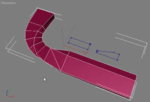
Lofting II
Ted Boardman tedb@tbmax.com http://www.tbmax.com
Fundamental Lofting Methods: Part II
Last month we had a look at the fundamentals of lofting a shape along a path in either Autodesk VIZ or 3ds max. In one of the exercises you lofted a rectangle along a path to create a small section of sidewalk, you then edited the path to fillet the corner resulting in a curved portion. Finally you optimized the mesh by changing Path and Shape Steps and by adding vertices to the curved segment of the path for more local detail.
| This month we will investigate lofting a little deeper. You will learn how to apply a handicap ramp to the sidewalk by lofting multiple shapes along the same path. Remember there is no limitation to the number of shapes on any given path or the number of vertices in each shape. However, each shape must have the same number of spines, for example you cannot loft a Donut shape (two splines) and a Circle shape (one spline) on the same path. |
|
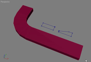
Figure 1: A rectangle lofted on a curved path to create a sidewalk |
In Figure 1 you will see the rectangle used last month to loft the curved sidewalk. The result is a rectangular cross-section along the entire walk.
There is a copy of the original rectangle that has been edited by adding a vertex and moving one corner to create a sloped section.
HINT: I’ve set the initial file up with a little glitch that will illustrate something that occurs quite often in lofting production and is one of the leading causes of users abandoning lofting as a tool in max or VIZ. Can you guess where there is a problem by looking at the shapes? I also selected the shapes and, in the Object Properties dialog, set Vertex Ticks on so you can see the shape’s vertices without being in sub-object Vertex mode.
|
Lofting Multiple Shapes on a Path
The process involved in lofting multiple shapes on a path is to simply go to a different level on the path and perform the Get Shape operation again. If you select a loft object and go to the Modify panel, there is a rollout called Path Parameters. See Figure 2.
|
|
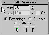
Figure 2: In the Modify panel of a selected loft object you will find Path Parameters rollout. |
It is set to 0 percent along the path as being the active level of the loft object. This is measured from the First Vertex of the loft path. There are options to measure the distance in display units Distance and Path Steps. In this case we have Path Steps set to 0 for optimization of the mesh, so each Path Step is a vertex along the path.
TIP: To find the length of a shape, select the shape, go to Utilities panel, and choose Measure. Using Measure on 3D objects will report surface area and volume.
In this example we will use Distance to determine the active level on the path. The number display in the Path field is now in feet and inches rather than in percent. If I enter 12’0” in the Path field a yellow tick on the path moves 12 feet along the path and that becomes the active level. See Figure 3. |
|
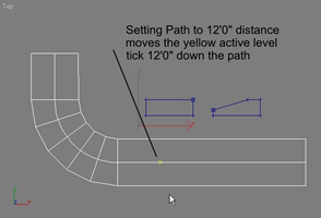
Figure 3: Changing the Path, Distance setting for the loft object moves the yellow tick from First Vertex to, in this case, 12’0” down the path. |
| In Modify panel I pick Get Shape and pick the new cross-section shape to set it at this level. The result, however, might not be exactly what you expect, let alone what you want. See Figure 4. |
|

Figure 4: Get Shape at the 12’0” level creates a nasty twist to the sidewalk. |
The twist is caused by the First Vertex position on the shapes. The First Vertex shows up as a box on a vertex in the viewport and, as you can see, they are not in the same relative position on each shape. (This is the glitch I introduced to illustrate a point). The lofting process analyzes the shapes on the path and connects the First Vertex of each shape, then it creates a new segment for each vertex and Shape Step setting, resulting in a 3D mesh.
|
To correct the problem I will select the sloped shape and go to Modify panel, sub-object Vertex. I select the upper right vertex and click the Make First button. Making the First Vertex on each shape in the same relative position takes the twist out of the loft. But it still doesn’t look the like a handicap ramp. The beginning of the sidewalk is rectangular, but it starts to slope immediately at the beginning and gradually transitions to the full slope at 12’0”.
What I need to do to correct this is to get the original rectangular shape at 12’0” to hold that cross-section for the first 12 feet., then in Path Parameters rollout, I enter 13’0”. At that level I do Get Shape and pick the sloped shape. See Figure 5.
|
|
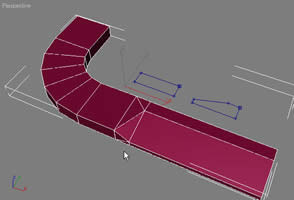
Figure 5: Get the original rectangular shape at 12’0”, set the Path level to 13’0” and get the sloped shape. This holds the rectangular cross-section for 12’ then slopes quickly in 1’. |
| Now I set the Path level at 16’0” and get the sloped shape again. This holds the sloped cross-section for 3 feet. Lastly, I set the Path level to 17’0” and get the original rectangular shape. This transitions from sloped to rectangular in 1 foot and holds the rectangular cross-section to the end of the path. See Figure 6. |
|
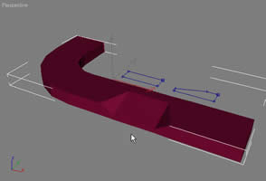
Figure 6: The sloped shape is at level 16’0” and the rectangular shape is at 17’0”. The handicap ramp is complete at the location I specified. |
The position of the ramp can be easily adjusted at any time to move or resize the ramp. There are two methods of adjusting the position of the shapes on the path.
First I can go to Modify panel, Stack view and select sub-object Shape for the selected loft object. It will turn red when selected. See Figure 7.
|
Once the shape you want to move is selected, the Path Level in the Shape Commands rollout shows the level it is currently on. All you have to do is type in the new distance that you want that shape to be on and hit Enter. The shape will move to the new position.
The other option is to select the shape or shapes while in sub-object Shape level, then click the Select and Move button and simply move the shapes along the path.
|
|
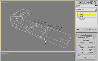
Figure 7: In Modify panel, Stack view, choose Shape sub-object level, and pick the shape on the path (not the original shape) that you want to move. It will turn red when selected. |
Work with some simple examples to get a feel for how lofting can be easily edited on the fly, which is not always so simple with other methods of modeling. The profile of the sidewalk could quickly be changed to add curbstones by adding vertices to the original shapes to create a grove near one edge. Edges can be chamfered or filleted for more detail and the sizes of the sidewalks can be altered quickly. Because the shapes are Instanced on the path, any modifications you make to the 2D shapes will be automatically applied to the entire sidewalk.
In a bit you will see some advantages that lofted objects have when it comes to applying materials and maps to the surface.
And another thing…
First I want to show an example of creating “clean” mesh objects with lofting. Remember I said each shape can have as many vertices as you want and each can have a different number of vertices.
| If I loft a Circle shape to a Star shape on a straight path I get a complex object. See Figure 8. The Circle has 4 vertices and the Star has 12 with 5 Shape Steps to interpolate the curvature. As you can see, the object is what you might expect, but if you look closely you will see that VIZ or max has to make some guesses as it transitions the surface from few points at the bottom to more points at the top. The result is a somewhat irregular surface that you don’t have complete control over. |
|
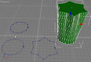
Figure 8: A Circle and Star lofted on a straight path. The program interpolates the topology of the surface to transition from 4 vertices at the bottom to 12 vertices at the top. |
It is often better to use shapes with the same number of vertices along the path for a much more regular surface. This will help eliminate surface glitches as the software determines the topology. In Figure 9, I have substituted a circular N-Gon shape with 12 vertices for the Circle at the bottom. The surface is much more regular and would be easier to optimize and to control the transitions between shapes.
|
Materials, Mapping, and Lofted Objects
You have seen some of the editing advantages of using lofted object with multiple shapes along the path. There are also some significant advantages of lofted objects when it comes time to apply materials.
What I want to do is apply expansion joints to the sidewalk, but I don’t want extra geometry. I will use a Bump map to give the illusion of joints while leaving the geometry as is. The map I will use in my material will be a Gradient Ramp map that is standard in VIZ and max. White areas of the map create bumps while black areas have no effect on the surface.
|
|
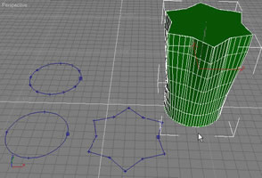
Figure 9: Substituting the Circle shape with 4 vertices with a N-Gon with 12 vertices results in a much “cleaner” mesh that can be better optimized and edited. |
In the Material Editor I assign as Gradient Ramp map to the Bump slot. In the Gradient Ramp I change the flags to black and white and set the Interpolation type to Solid. See Figure 10. Moving the white flag to the left results in a white field with a thin black line along the left edge. I also entered 90 in the W: Angle field in the Gradient Ramp Coordinates rollout, to rotate the map 90 degrees.
|
TIP: In max and VIZ there is a handy formula…XYZ=UVW. Both axis designators mean the same thing. UVW is used for materials but were chosen just because they are the next three letters in the alphabet.
In the Gradient Ramp level of Material Editor I turn on the Show Map in Viewport toggle so I’ll see the Ramp on the object in the shaded viewport. It appears as a white sidewalk with a thin black strip at one end.
|
|
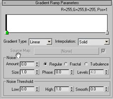
Figure 10: A Gradient Ramp map with black-white-white flags and Interpolation set to Solid. The map is rotate 90 degrees in the W axis. |
I select the loft object and, in the Modify panel, Surface Parameters rollout, I enter 8.0 in the Length Repeat field of the Mapping area. This repeats the black-white pattern over the length of the sidewalk loft object. See Figure 11. When rendered the black becomes an indented expansion joint in the surface of the sidewalk. It only simulates the indentation and does not add much overhead to your rendering time.
|
In Summary
It is safe to say that I am a rabid proponent of lofting in 3ds max and Autodesk VIZ. It offers unprecedented control in the density of the mesh, the variations of cross-section shapes along the path, and special control for material mapping coordinates that are not found elsewhere.
Major changes in your geometry can be accomplished by simple tweaking of the 2D shapes that make up the loft shapes resulting in a freedom of design that you don’t get with other modeling methods in VIZ or max or certainly in most CAD software.
|
|
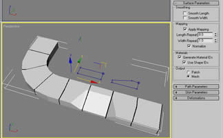
Figure 11: In Modify panel, Surface Parameters rollout, for the lofted object, the Length Repeat adjusts the number of repetitions of the map along the length of the path. |
Uses for lofting can range from roads and walks, to counters and cabinets, to complete multi-story facades of buildings. Lofting is often my choice for modeling even if there is a faster way to create the object initially because of the flexibility it offers.
Learn how to use it, then you can make an informed choice on how best it might fit into your workflow.
Good luck and have fun.
Ted
Download Sample Files HERE (34KB)


